
Overmolded Cable Assembly Manufacturing for Australia
Custom overmolded cable assemblies for Australian OEMs. Define jacket adhesion, cable exit geometry and environmental validation for your mining, marine, automotive or industrial application.
Quick answer
Overmolding forms a protective body around a cable-to-connector junction. It can support the cable exit and help seal the interface, but neither the moulded shape nor the material name guarantees adhesion, flex life or waterproof performance. An IP rating belongs to the finished mated assembly in its specified test configuration and method, not to the overmold alone.
| Code | Meaning | What to specify |
|---|---|---|
| IP6X | The first digit 6 means dust-tight. X leaves the water digit unspecified. | The enclosure boundary, mating parts and dust test configuration |
| IP67 | Dust-tight plus temporary immersion. For a compact assembly, the IPX7 test places its lowest point 1 m below the water surface for 30 min. | Assembly orientation, cable ends and mated connector/seal configuration; use the applicable IEC 60529 geometry and method |
| IP68 | Dust-tight plus immersion under conditions agreed between buyer and maker, more severe than IPX7. | State the agreed depth and duration. For service beyond 1 m or longer than 30 min, specify both; the code alone does not supply those values |
Immersion testing does not establish resistance to water jets, saltwater, chemicals or flexing. Define those exposures separately in the waterproof harness specification.
What is Overmolded Cable Assembly?
Overmolding forms a thermoplastic or thermoset body around the junction between a cable and its connector. The tool controls the external shape while fixtures hold the connector and cable in position. The jacket-to-overmold interface remains a critical part of the sealing design.
The overmold can support the cable exit and limit access to terminations. Water ingress, vibration, chemical exposure and UV resistance require their own material choices and acceptance tests. A smooth outer surface is not evidence of a bonded, void-free interface.
For equipment exposed to heat, dust, moisture or vibration, define the service conditions before choosing the compound. Include mating seals and exposed cable ends in the review, because the overmold cannot protect a water path elsewhere in the assembly.

Why Australian Engineers Choose Overmolded Cable Assemblies
Define the failure modes and validation evidence before selecting an overmold design
Specified Ingress Protection
Set an ingress target for the finished mated assembly. Immersion and pressure washdown are different exposures; name the applicable test method and conditions for each.
Cable Exit Strain Relief
The cable exit geometry can spread bending over a longer transition. Validate the bend direction, jacket support and connector retention under the specified flex and vibration conditions.
Temperature Compatibility
Temperature limits are set by the specific compound datasheet and the cable and connector ratings. The assembly requirement is confirmed per drawing at quotation, including thermal cycling where specified.
Covered Terminations
A moulded body limits access to the terminations. Agree the repair or replacement approach, identification and traceability requirements before approving the geometry.
Defined Pull Strength
Pull-force requirements are confirmed per drawing at quotation. The test must define the grip, load direction and acceptance criteria; record whether failure occurs at the bond, jacket or connector retention feature.
Chemical & UV Resistance
Select compounds against the actual fluids and outdoor exposure. Record concentration, temperature and exposure method in the validation plan rather than assuming resistance from the polymer family.
Overmolding vs. Alternative Protection Methods
Compare overmolding against heat shrink, potting, and backshell solutions to find the right fit for your application
| Feature | Overmolding | Heat shrink | Potting | Backshell |
|---|---|---|---|---|
| Sealing approach | Validate jacket bond and connector interface | Validate tubing, liner and end seals | Validate resin adhesion, fill and housing seals | Validate glands, gaskets and mating interfaces |
| Strain relief | Shaped cable exit and insert retention | Tubing support; additional anchoring may be needed | Anchoring and exit support depend on housing design | Cable clamp and exit support depend on hardware |
| Pull strength | Confirmed per drawing at quotation | Confirmed per drawing at quotation | Confirmed per drawing at quotation | Confirmed per drawing at quotation |
| Access for repair | Removal may damage the body or cable | Tubing normally needs replacement | Depends on resin and access to the cavity | May be opened if the design permits |
| Cost drivers | Tooling, handling and moulding cycle | Tubing, adhesive and installation steps | Resin, dispensing and curing | Housing, gland, clamp and assembly labour |
Not sure which protection method suits your application?
Read Our Detailed Comparison GuideOvermold Materials & Technical Specifications
Overmold Material Options
A candidate for general-purpose moulded bodies. Confirm plasticiser compatibility, jacket adhesion and the specific compound temperature rating per drawing at quotation.
A candidate where abrasion and flexing matter. Check the selected grade against fluids, moisture and jacket adhesion; temperature rating is confirmed per drawing at quotation.
A broad family for compliant grips and cable exits. Confirm the exact grade, application documentation and bond performance; temperature rating is confirmed per drawing at quotation.
A candidate for a stiffer body. Check processing heat, moisture conditioning and cable-exit stiffness; temperature rating is confirmed per drawing at quotation.
Check cure compatibility, adhesion preparation and tear resistance for the chosen grade. Temperature rating is confirmed per drawing at quotation using its datasheet.
Manufacturing Specifications
Connectors We Overmold
Jacket-to-overmold bond: which material pairs bond and what to validate
Confirm the compound pair before freezing the tool. A jacket and overmold can share a polymer family yet behave differently because of additives, surface contamination or processing. PUR is a polyurethane family label; verify whether the jacket is thermoplastic TPU and obtain its exact grade.
| Cable jacket / overmold → | PVC | TPU | TPE | Nylon | Silicone |
|---|---|---|---|---|---|
| PVC | confirm by sample | confirm by sample | confirm by sample | confirm by sample | confirm by sample |
| PUR (TPU grade to confirm) | confirm by sample | confirm by sample | confirm by sample | confirm by sample | confirm by sample |
| TPE | confirm by sample | confirm by sample | confirm by sample | confirm by sample | confirm by sample |
| Silicone | confirm by sample | confirm by sample | confirm by sample | confirm by sample | confirm by sample |
| PTFE / FEP, untreated | poor adhesion, use mechanical lock-in | poor adhesion, use mechanical lock-in | poor adhesion, use mechanical lock-in | poor adhesion, use mechanical lock-in | poor adhesion, use mechanical lock-in |
Source scope: Avient's GLS TPE Overmolding Guide, Adhesion Requirements, and Overmolding: Processing explain grade-specific adhesion and the effects of additives, moisture, preparation and process conditions. Zeus's Custom Etching guidance identifies the bonding difficulty of untreated PTFE/FEP and surface treatment as an option. These sources do not certify the material pairs in this matrix; unspecified pairs therefore remain “confirm by sample”. Mechanical lock-in provides retention, not proof of a water seal. If a supplier proposes treatment or primer, qualify that process and check the treated surface on first articles.
First-article bond validation checklist
- Record both compound grades, cable lot, surface preparation, primer if used, colour masterbatch and moulding conditions. The final pair is confirmed by a first-article test, not this screening matrix.
- Perform the agreed peel or pull test on first articles. Define the grip, direction, speed, conditioning and limit on the drawing; record adhesive separation, jacket tearing or mechanical pull-out. Pull force alone can hide a weak bond behind a retention feature.
- Thermally cycle designated samples to the drawing or customer specification, then repeat the agreed bond and sealing checks. Record the temperature profile and sample history.
- Cut-section designated samples to inspect voids, incomplete wetting and gaps along the jacket interface. Perform destructive sectioning after the required functional tests or on separately identified samples.
- Repeat the agreed validation when the compound, cable supplier, surface preparation or moulding process changes in a way that could affect the bond.
The cable overmolding design guide connects material selection to connector retention and cable-exit geometry.
Tolerances that decide whether the mold works
Design the cable shut-off around the supplied OD envelope, including ovality. A bore that accommodates a large cable may leave a flash path around a small one; a tighter shut-off can mark or compress the jacket. Inspect samples at the tolerance extremes before approving the tool.
Assumed example, not a standard limit
Assume a circular cable OD of 6.0 mm ± 0.3 mm. For illustration only, choose a fixed bore with 0.1 mm diametral clearance over the largest cable. This arithmetic ignores bore manufacturing tolerance, ovality and jacket compression; it is not a recommended shut-off clearance.
| Quantity | Arithmetic | Implication |
|---|---|---|
| Minimum cable OD | 6.0 − 0.3 = 5.7 mm | Smallest cable in the assumed envelope |
| Maximum cable OD | 6.0 + 0.3 = 6.3 mm | Largest cable in the assumed envelope |
| Assumed fixed bore | 6.3 + 0.1 = 6.4 mm | Illustrative clearance rule, not a production recommendation |
| Diametral gap at largest cable | 6.4 − 6.3 = 0.1 mm | The assumed bore still has a gap |
| Diametral gap at smallest cable | 6.4 − 5.7 = 0.7 mm | Larger gap can permit resin escape; rework the shut-off strategy |
A toolmaker may propose matched inserts, a compliant shut-off or tighter incoming cable control. Evaluate flash and jacket damage together; do not copy this clearance into a drawing. Actual bore limits are confirmed per drawing at quotation.
| Interface | Define on the drawing | Check before approval |
|---|---|---|
| Cable OD versus mould bore | OD tolerance, ovality, cable datum and shut-off region | Incoming cable extremes, bore/insert tolerance and jacket compression |
| Flash and parting line | Permitted parting-line location, flash limit and seal/latch keep-outs | Trimmed and untrimmed samples; flash must not obstruct mating or hide a damaged jacket |
| Wire exit position | Exit centreline and angle from connector datums; allowed motion and bend direction | Fixture location, off-centre cable and wall coverage around the exit |
| Connector pocket clearance | Insert envelope and tolerance, locating faces, retention and areas to keep resin-free | Connector movement under injection pressure, latch travel and mating engagement |
| Shrinkage and warpage | Specific compound datasheet and agreed dimensional conditioning | Material-dependent shrinkage can alter pocket fit and cable grip; confirm finished dimensions after the specified conditioning |
Combined flex + waterproof validation
Test sealing after flexing the same identified assembly. Testing a new sample for immersion and a different sample for flexing cannot show whether movement opened a leak path. The sequence below is a proposed validation plan to agree with the buyer, not a sequence prescribed by IEC 60529.
| Condition / order | What is checked | Record to retain |
|---|---|---|
| Baseline, before conditioning | Visual condition, continuity and specified electrical baseline; verify mating seals and cable-end treatment | Sample and lot IDs, drawing revision, mating parts, photographs, instruments and baseline readings |
| Thermal conditioning, if required by the plan | Bond and jacket behaviour under the specified temperature profile | Temperature, dwell, cycle count, sequence position and observations; all parameters from the agreed specification |
| Flex cycling on the identified assembly | Cable exit, connector retention and continuity during motion where specified | Fixture, bend radius, angle, load, rate, cycles, environment and interruptions; limits from the drawing |
| Immersion after flexing | Ingress in the specified mated configuration, using the applicable IEC 60529 method | Depth, duration, water and sample conditions, mating configuration, time since flexing and observations |
| Post-immersion electrical checks | Insulation resistance, dielectric withstand (hi-pot) and continuity as required by the control plan | Specified wet/recovery condition, elapsed time, voltage, duration, leakage/resistance readings and acceptance decision |
| Final examination, then destructive analysis if specified | Cracks, jacket separation, voids and possible water paths | Inspection images, cut-section locations, failure location and disposition linked to sample ID |
Fix the recovery and drying conditions before testing: unrecorded drying can change the post-immersion electrical result. Hi-pot suitability and electrical isolation must be agreed for assemblies containing electronics. Keep destructive bond tests and sectioning until after the functional sequence, or use separately identified samples. An immersion check alone does not establish the dust portion of an IP rating. Arrange the scope through testing and validation.
| Assembly / revision / lot / sample ID | Jacket / overmold grades | Mating parts / cable ends | Stage / order / method | Specified parameters / limits | Actual conditions / recovery time | Instrument / calibration | Reading / observation / file reference | Pass or fail / disposition | Operator / date |
|---|---|---|---|---|---|---|---|---|---|
| — | — | — | — | — | — | — | — | — | — |
Tooling cost structure
Quotes show tooling separately from piece price. Agree what the tool charge includes and what triggers a revision charge before release. Quantities, capability limits and schedules are confirmed per drawing at quotation.
| Cost line | What drives it | What the quote should state |
|---|---|---|
| Mould base and cavities | Part geometry, cavity count, slides, gates, cooling and interchangeable inserts | Tool scope, ownership, maintenance, storage and change responsibility |
| Rapid versus production tooling | Development changes, expected repeat demand, tool material and wear requirements | Intended use, limitations and whether later production tooling is a separate charge |
| Insert and holding fixture | Connector location, cable OD variation, shut-offs and manual loading access | Included fixtures, replaceable inserts and allowance for cable or connector variants |
| First-article samples and validation | Material trials, dimensional inspection, destructive samples and the agreed test sequence | Included sample scope, reports, approval criteria and treatment of repeat trials |
| Material and colour matching | Specific compound, masterbatch compatibility, drying, changeovers and colour approval | Approved grades, colour reference, trial charges and material substitution controls |
| Cycle time and piece price | Loading, filling, cooling or curing, demoulding, trimming and inspection | Recurring operations included in piece price and the volume basis of the quotation |
Compare the full build and validation scope when considering overmolding versus potting; a tooling charge alone does not describe the cost of the finished assembly.
Our Overmolding Manufacturing Process
From design consultation to validated production, our streamlined process delivers overmolded cable assemblies with confidence
Design Review
Analyse connector, cable, and environment requirements
Material Selection
Choose optimal overmold compound for your application
Mould Design
CAD design and CNC machining of custom overmold tooling
Prototype
First article overmolded samples for validation
Testing
IP rating, pull force, environmental, and electrical tests
Production
Visual, dimensional and electrical checks per the control plan agreed on the drawing
Overmolded Cable Assembly Applications
Application requirements guide the material choice, geometry and validation plan
Mining & Resources
Sensor cables, power connectors and communication harness enquiries for mining equipment. Specify dust, immersion, vibration, hydraulic fluid and washdown requirements separately.
View Industry SolutionsMarine & Offshore
Cable enquiries for vessel electronics, navigation and offshore equipment. Specify saltwater, UV, mating-seal and installation requirements for validation.
View Industry SolutionsAutomotive & EV
Engine bay, EV battery management and sensor harness enquiries need application-specific requirements. Certificates are held by the Hebei Cloom factory; see the Quality section.
View Industry SolutionsMedical Devices
Medical cable enquiries require the intended contact, cleaning and sterilisation conditions. Material documentation and finished-device validation must support the intended use.
View Industry SolutionsIndustrial Automation
Sensor cables, robotic harnesses and PLC communication cable enquiries. Define flex motion, fluid exposure and vibration conditions for the proposed assembly.
View Industry SolutionsQuality Assurance & Certifications
Certificates shown here are held by the Hebei Cloom factory. Product inspection and release follow the control plan agreed on the drawing; factory certification does not establish an assembly IP rating.
ISO 9001:2015
Quality Management System

IATF 16949:2016
Automotive Quality Management
Overmold Testing & Validation
IP Rating Validation
Finished-assembly testing to the specified IEC 60529 rating, mating configuration and agreed conditions
Pull Force Testing
Pull testing against the force, fixture, direction and acceptance criteria named on the drawing
Thermal Cycling
Temperature profile, dwell and cycle count are confirmed per drawing at quotation
Electrical Testing
Continuity, insulation resistance and hi-pot checks per the control plan agreed on the drawing
Our Manufacturing Facility

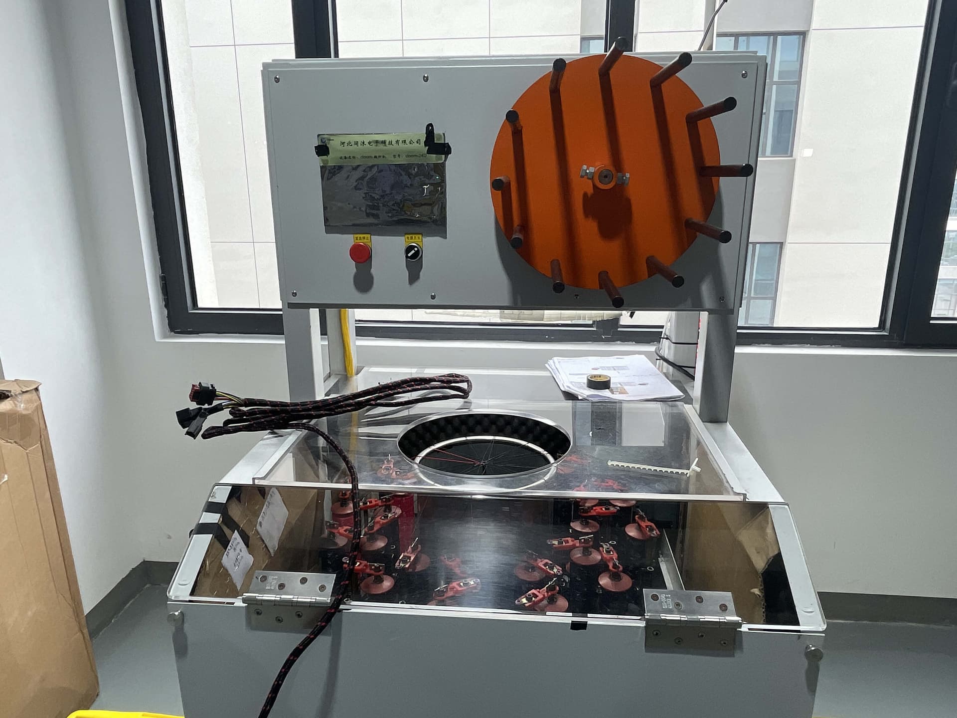
Cable Braiding & Preparation
Cable preparation and geometry checks support the specified overmold process.

Precision Soldering Station
Soldered terminations are inspected against the specified workmanship requirements before overmolding.

Comprehensive Testing Lab
Electrical, mechanical and environmental validation is defined by the agreed control plan.

Automated Vision Inspection
Inspection checks cover surface quality, flash and dimensions using the methods agreed on the drawing.
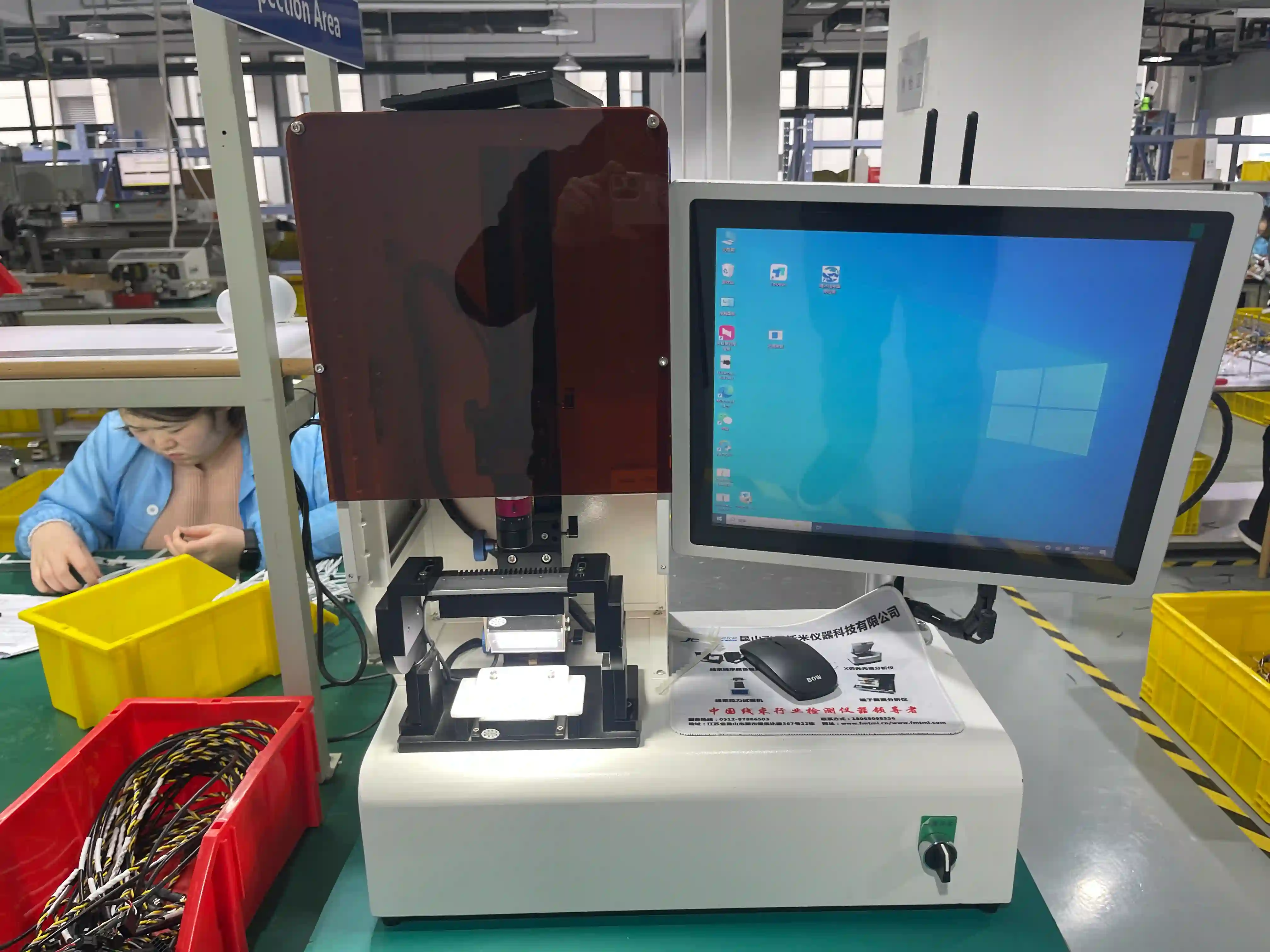
Quality Control Area
Dedicated QC stations for incoming material inspection and final product release.
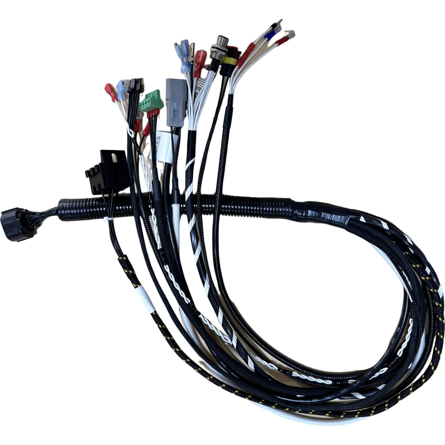
Prototype Development
First-article samples support geometry and material validation. Timing is confirmed per drawing at quotation.
Documents to agree before tooling and production
| Purchasing stage | Document to request | Decision it supports |
|---|---|---|
| Quotation | Drawing revision, cable and connector datasheets, quantities, tooling scope and separate piece price | Resolve missing tolerances, material grades and test requirements before costing |
| Tooling release | Approved geometry, cable OD envelope, mating keep-outs, cavity/insert plan and tool ownership terms | Approve the design and responsibility for changes, maintenance and storage |
| First-article approval | Dimensional report, compound and cable lot references, bond checks and combined flex/ingress/electrical records | Accept the actual material pair and process against the specified criteria |
| Production release | Control plan, sampling and test coverage, acceptance limits, traceability and change-control rules | Define what is inspected and tested per lot or unit, and what triggers revalidation |
| Delivery | Agreed inspection records, lot identification and deviations approved against the drawing revision | Match supplied assemblies to the approved configuration |
Use the engineering drawing review to close missing inputs before releasing the tool.
Frequently Asked Questions About Overmolded Cable Assemblies
Have a technical question about overmolding?
Speak with Our Overmolding EngineerRelated Resources
Related Articles
Overmolded vs Potted Cable: Which to Choose?
Detailed comparison of overmolding and potting for cable protection.
Cable Assembly Strain Relief Guide
Complete guide to strain relief methods including overmolding techniques.
Wire Harness Environmental Protection
Methods for protecting wire harnesses from harsh environments.
Related Capabilities
Get an Overmoulded Cable Quote
Send your drawing, wire list or BOM — an engineer replies with a quote and lead time within 24 hours.
Ready to Overmold Your Cable Assembly?
Send us your connector and cable specifications. Our engineering team will recommend the optimal overmold design, material, and tooling approach for your application.
Tooling, order quantity and schedule are confirmed per drawing at quotation.