
Micro Coaxial Cable Assembly Manufacturing for Australia
Custom micro coaxial cable assemblies for compact imaging systems, medical devices, display modules, embedded electronics, RF products, and high-density equipment where standard coax is too large or too stiff.
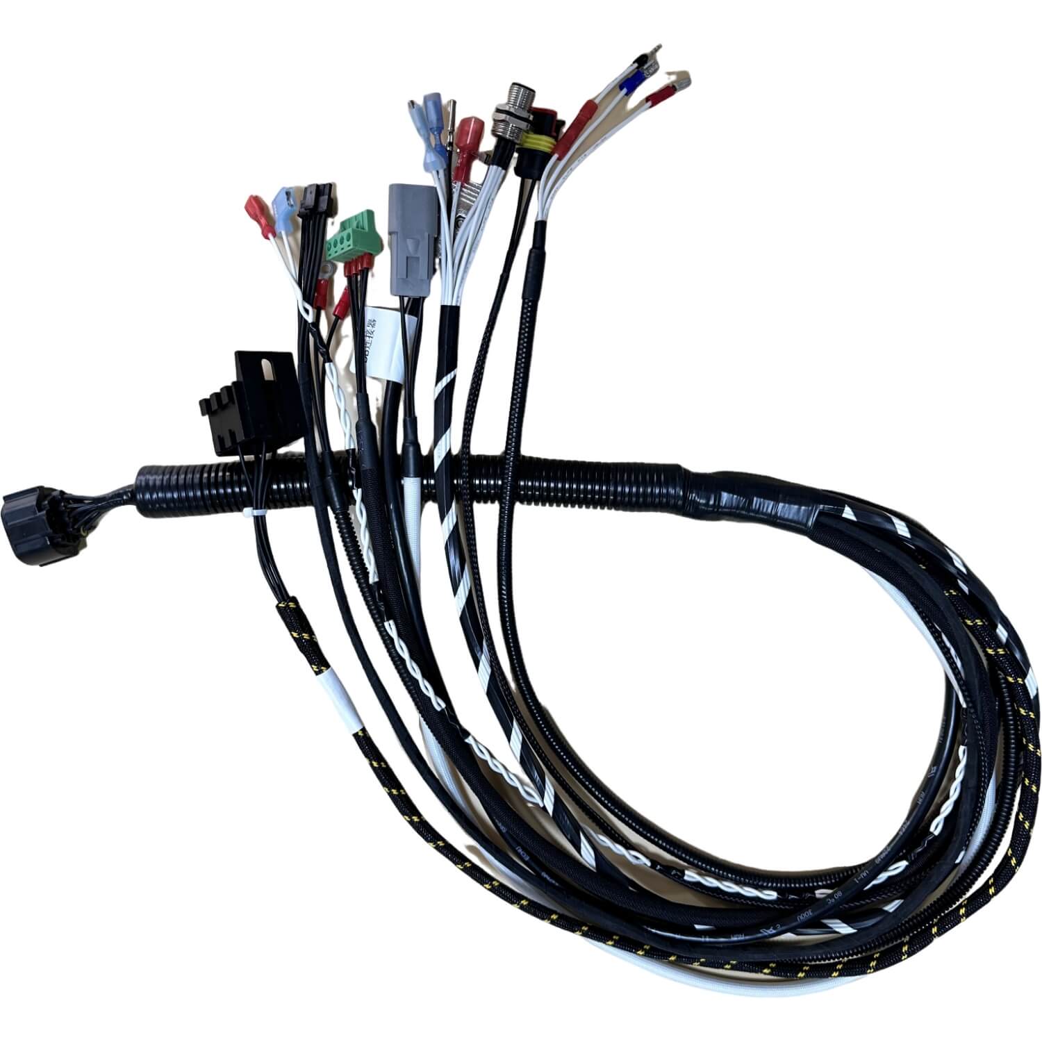
Why micro coax assemblies matter when standard coax is too large
Micro coaxial cable assemblies are selected when designers need the shielding and signal stability of coaxial construction but cannot tolerate the size, stiffness, or routing penalty of larger cable families. That situation is common inside compact medical devices, imaging modules, embedded electronics, telecom hardware, and other products where every millimetre of package space matters.
The engineering challenge is that miniature cable is less forgiving. Small conductor and dielectric dimensions demand tighter stripping control, more careful shield preparation, and better strain management at the connector. Concepts such as coaxial cable construction,characteristic impedance, and insertion loss explain why small processing errors can affect performance.
For programs that also include more conventional RF cabling, our related SMA cable assembly capability covers larger 50 ohm coax builds, while our medical and telecom pages show the environments where compact shielded interconnects are most often needed.
For compact medical devices, review the mating interface alongside our medical connector manufacturing page. For display and internal module routing, compare FFC cable assembly options against the shielding, signal, and bend requirements before selecting the interconnect.
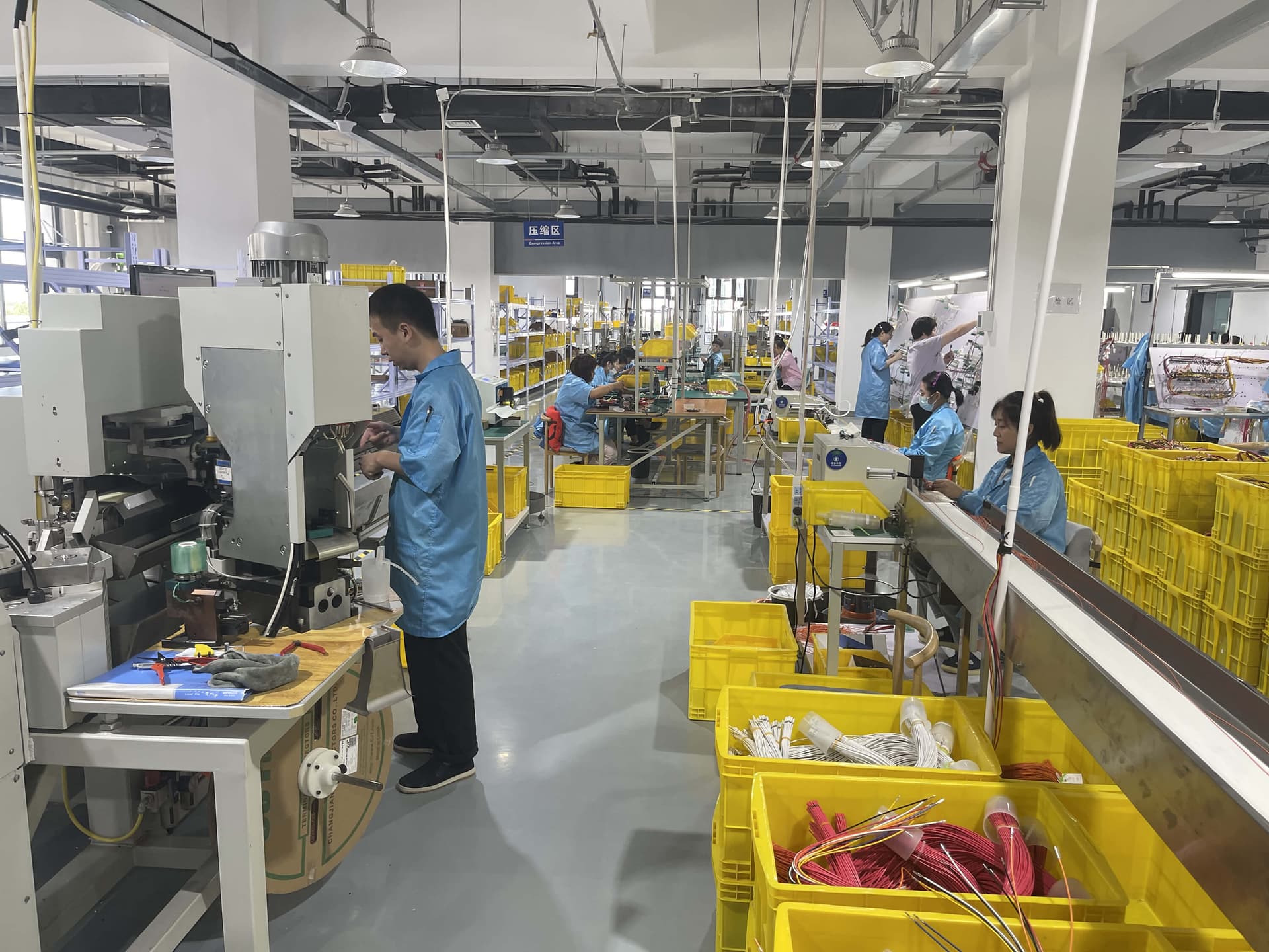
What buyers usually need from a micro coax supplier
The requirement is usually not just small cable. It is controlled miniature processing, repeatable routing, and stable signal performance in a dense package.
Processing Control for Very Small Cable Geometry
Micro coax assemblies demand tighter stripping, trimming, shield preparation, and termination control than standard coax because the materials are smaller and less forgiving.
Built for Dense Packaging and Tight Bend Space
We align cable choice, connector orientation, and route geometry to compact product enclosures where ordinary coax is too large or too stiff.
Shielded Signal Paths for Sensitive Electronics
Micro coax is often selected to preserve shielding and cleaner signal transmission in compact assemblies carrying imaging, RF, or low-level electronic signals.
Length and Routing Defined Around the Actual Hardware
In miniature electronics, a few millimetres can decide whether the assembly installs cleanly or creates strain at the connector. We build around the real route, not an abstract nominal length.
Prototype, Replacement, and Production Support
We support sample-based reverse engineering, first articles, and controlled repeat supply when a compact coax assembly needs to move from lab validation to purchasing.
Inspection Matched to Signal and Reliability Risk
Finished builds are checked to the agreed workmanship and electrical criteria, with signal-performance validation added where the program requires it.
Technical scope we commonly support
| Typical Use Cases | Miniature imaging, display links, RF modules, handheld devices, compact medical electronics, telecom modules, and dense internal equipment wiring |
|---|---|
| Cable Scale | Small-diameter coax constructions selected around signal integrity, bend radius, routing density, and connector compatibility |
| Signal Support | RF, video, data, and shielded low-level signal paths where controlled impedance and compact packaging matter |
| Shielding Options | Miniature coax shield constructions with termination strategies defined around EMI and signal integrity requirements |
| Termination Styles | Micro connectors, board-level interfaces, pigtails, mixed-end builds, and customer-specified compact terminations |
| Validation Options | Continuity, pinout, workmanship, retention, shielding verification, and signal-performance checks where specified |
| Mechanical Focus | Tight bend-space review, strain relief control, service-loop definition, and handling protection for delicate assemblies |
| Production Scale | Prototype quantities through repeat OEM supply with revision-controlled build documentation |
Design review checklist
Confirm the actual cable diameter or family early because connector choice and stripping process depend on it.
Define impedance, signal type, and route length together if the assembly is performance-sensitive.
Review minimum bend space and service-loop needs before freezing the finished length.
Specify whether the assembly is internal-only, field-serviceable, or subject to repeated flexing because that changes the strain-relief approach.
Document connector orientation and polarity clearly on dense multi-cable builds to reduce assembly and service errors.
Separate workmanship checks from electrical or RF checks so incoming inspection knows exactly what was verified.
State the cable part number or the shield-to-centre-conductor diameter ratio D/d and dielectric material.
State any DC bias or current on the centre conductor and the allowable voltage drop.
State the test frequency range and acceptance criteria; test scope can be specified; scope agreed at quotation.
State whether bending is static routing or dynamic flexing, including the route and strain-relief requirements.
Micro coax numbers every drawing should settle
Geometry, dielectric, conductor size, and operating frequency help define the drawing. The reference values below explain the design checks; the selected cable datasheet defines the assembly inputs.
Impedance starts with geometry and dielectric
Source: Wikipedia: Coaxial cable. The relation below describes the low-loss coax model with a uniform dielectric; the approximation applies to non-magnetic materials.
| Quantity | Relation or meaning |
|---|---|
| Characteristic impedance | Z0 = (1/2π)√(μ/ε) ln(D/d) ≈ (59.96 Ω/√εr) ln(D/d) |
| Diameters | D = shield (outer conductor) inner diameter; d = centre conductor diameter. Use matching units. |
| Material properties | μ = permeability; ε = permittivity; εr = relative permittivity of the dielectric. |
| PTFE reference | Velocity factor ≈0.70; εr ≈ 1/0.70² ≈ 2.04 (derived). |
Impedance worked example — assumed numbers, not a product spec
With εr = 2.04, substitute each diameter ratio into (59.96 Ω/√2.04) ln(D/d).
| D/d | Impedance |
|---|---|
| 3.0 | ≈46.1 Ω |
| 3.35 | ≈50.7 Ω |
| 3.5 | ≈52.6 Ω |
| ≈3.29 | Exactly 50 Ω target |
A few percent of dimensional variation moves impedance by a few ohms, so strip and termination tolerances matter on miniature cable.
AWG centre-conductor reference
Source: Wikipedia: American wire gauge. Diameter formula: d = 0.127 mm × 92^((36−n)/39), where n is the AWG size.
| AWG | Diameter | DC resistance | Diameter basis |
|---|---|---|---|
| 36 | 0.127 mm | 1361 mΩ/m | Tabulated |
| 38 | 0.101 mm | 2164 mΩ/m | Tabulated |
| 40 | 0.0799 mm | 3441 mΩ/m | Tabulated |
| 42 | 0.0633 mm | not tabulated here | Computed from formula |
| 44 | 0.0502 mm | not tabulated here | Computed from formula |
| 46 | 0.0398 mm | not tabulated here | Computed from formula |
AWG is only a conductor size reference; the cable datasheet defines the actual construction.
Skin depth makes the conductor surface important
Source: Wikipedia: Skin effect.
| Frequency | Skin depth |
|---|---|
| 1 MHz | 65.2 µm |
| 1 GHz | 2.06 µm |
A 40 AWG conductor has a radius of ≈40 µm (0.0799 mm / 2). At GHz frequencies, current is concentrated in a very thin surface layer, so plating and surface condition of a tiny conductor matter.
Wikipedia: Coaxial cable also explains that losses rise with frequency and that, at higher frequencies, the RF signal is carried by the plating on a plated conductor.
DC worked example — assumed numbers, not a product spec
Using the solid copper resistance from the AWG table, voltage drop = current × resistance per metre × length. For 1 m of 40 AWG centre conductor at 3441 mΩ/m carrying 100 mA, the drop is 0.344 V, which is ≈10.4 % of a 3.3 V rail.
Bias or power on a micro coax centre conductor needs an explicit voltage-drop check. This example covers the centre conductor only; include return-path and contact resistance in the complete circuit check and use the selected cable datasheet for the actual construction.
Data to put on a micro coax quote request
Put the cable, mating, routing, and acceptance requirements together so the drawing and quote describe the same assembly.
| Data field | What to include |
|---|---|
| Cable family / OD | Cable part number or family and overall outside diameter. |
| Centre conductor AWG | Conductor size, solid or stranded construction, and material or plating from the datasheet. |
| Dielectric | Dielectric material and cable datasheet reference. |
| Shield type | Shield construction and termination requirements. |
| Connector part numbers, both ends | Exact connector and mating references, orientation, and pinout. |
| Finished length and tolerance | Measurement datums, finished length, and allowable variation. |
| Impedance target | Nominal impedance and acceptance criteria. |
| Frequency range | Operating band and the frequency range required for any signal checks. |
| Bend / flex requirement | Route, bend constraints, strain relief, and whether movement is static or dynamic. |
| DC bias / current, if any | Bias voltage, centre conductor current, return path, and allowable voltage drop. |
| Inspection and test scope | Workmanship, continuity, pinout, shielding, and signal checks can be specified; scope agreed at quotation. |
| Marking / packaging | Identification, revision marking, and protection for cable and miniature terminations. |
Application areas for custom micro coaxial cable assemblies
Compact coax assemblies show up wherever multiple shielded signal paths need to fit into a small and repeatable package.
Miniature Cameras and Imaging Modules
Compact coax assemblies for internal video links, machine vision modules, portable imaging systems, and other products where size and shield continuity are critical.
Display and Embedded Electronics
Internal interconnects for displays, compact control modules, HMI equipment, and dense electronics where multiple small shielded lines must route through narrow spaces.
Medical and Diagnostic Devices
Miniature signal assemblies for patient-facing electronics, imaging tools, and compact devices that need precision handling, repeatability, and traceable build control.
RF, Wireless, and Telecom Modules
Small coax interconnects for antenna subsystems, embedded radio modules, telecom hardware, and compact communication electronics.
Replacement and Legacy Support
Second-source or reverse-engineered micro coax assemblies for imported electronics, ageing equipment, and custom modules where the original cable is difficult to source.
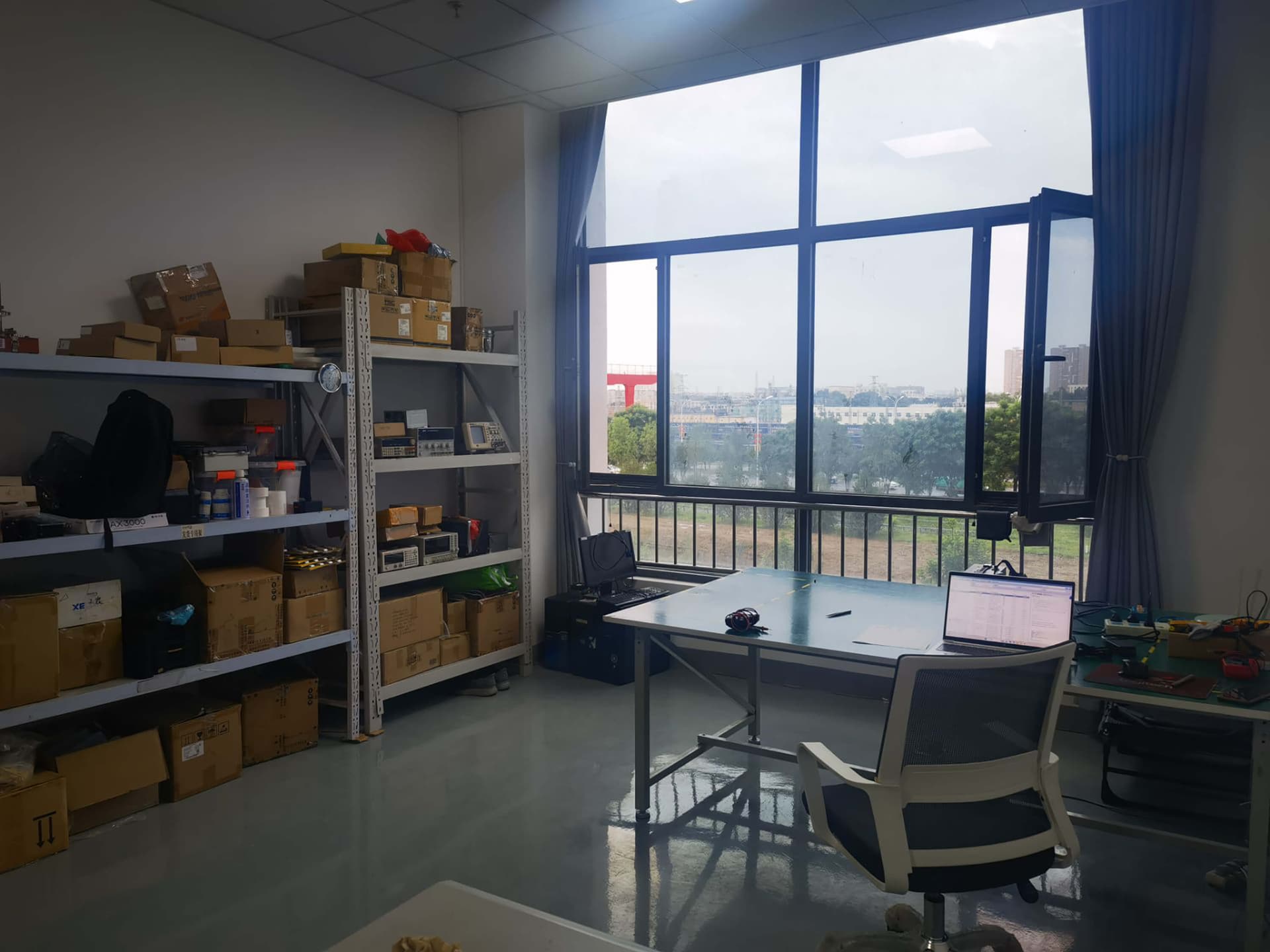
Our build process for micro coax programs
Application and Space Review
We review signal type, cable diameter, impedance needs, connector family, bend constraints, mating space, and environment before defining the assembly approach.
Cable and Connector Selection
Our team confirms the micro coax construction, termination style, shielding treatment, and strain-relief strategy around the real hardware package and performance target.
Prototype and First-Article Build
Initial assemblies are produced for fit, route, handling, and electrical confirmation so the part can be corrected before production release.
Controlled Production
Assemblies are processed with tight workmanship control for stripping, termination, labeling, and visual inspection to protect consistency across batches.
Verification and Release
Finished assemblies are verified to the agreed criteria, packed to protect the miniature terminations, and released with repeat-order documentation.
Validation focus on miniature signal assemblies
Micro coaxial cable assemblies often fail at the interface between tiny cable geometry and handling stress. That is why routing, strain relief, connector support, and workmanship definition matter just as much as the nominal electrical spec.
For many projects, the right release package includes continuity and pinout checks, visual inspection under controlled criteria, and additional shielding or signal checks based on the application risk.
If the program also needs larger shielded interconnects, overmolded exits, or broader system-level harnessing, we can align the micro coax assembly with the surrounding cable architecture during quotation.
Related references and internal capability links
A concise reference for coax structure, shielding, and signal-carrying behaviour.
Skin effect and copper skin depthReference for current concentration near the conductor surface as frequency rises.
American wire gauge referenceConductor diameter formula and tabulated solid copper resistance values.
Coaxial cable assembly capabilityUseful when the buyer is still choosing impedance, cable family, connector interface, and RF test criteria.
SMA cable assembly capabilityRelevant when your product also includes larger RF or antenna cable assemblies.
RF connector types guideUseful background when connector selection is still being finalised.
Testing and quality capabilityOverview of electrical verification and production quality processes.
How a typical micro coaxial cable assembly manufacturing program runs with us
This is an illustrative description of a representative project type, not a specific customer engagement. As a contract assembler we do not publish customer-identifiable data.
Micro coaxial cable assembly FAQs
Buyer questions we hear most often when compact shielded signal assemblies move from engineering to procurement.
A micro coaxial cable assembly is a very small-diameter coax interconnect designed for high-density signal transmission where space, weight, and bend radius are tightly constrained. It combines miniature coax cable, precision stripping and termination, controlled shielding, and compact connector interfaces into a repeatable assembly for electronics, imaging, RF, and high-speed data systems.
Need a quote for a micro coaxial cable assembly?
Send the cable sample, connector references, route photo, or drawing. We can review the miniature termination risk, routing limits, and build approach before the program moves into prototype or repeat supply.