
Dupont Cable Assembly Manufacturing for Australia
Custom Dupont-style cable assemblies for embedded electronics, lab equipment, test fixtures, educational kits, and low-voltage controls. Built with exact pin maps, controlled housing positions, and production-ready electrical verification.
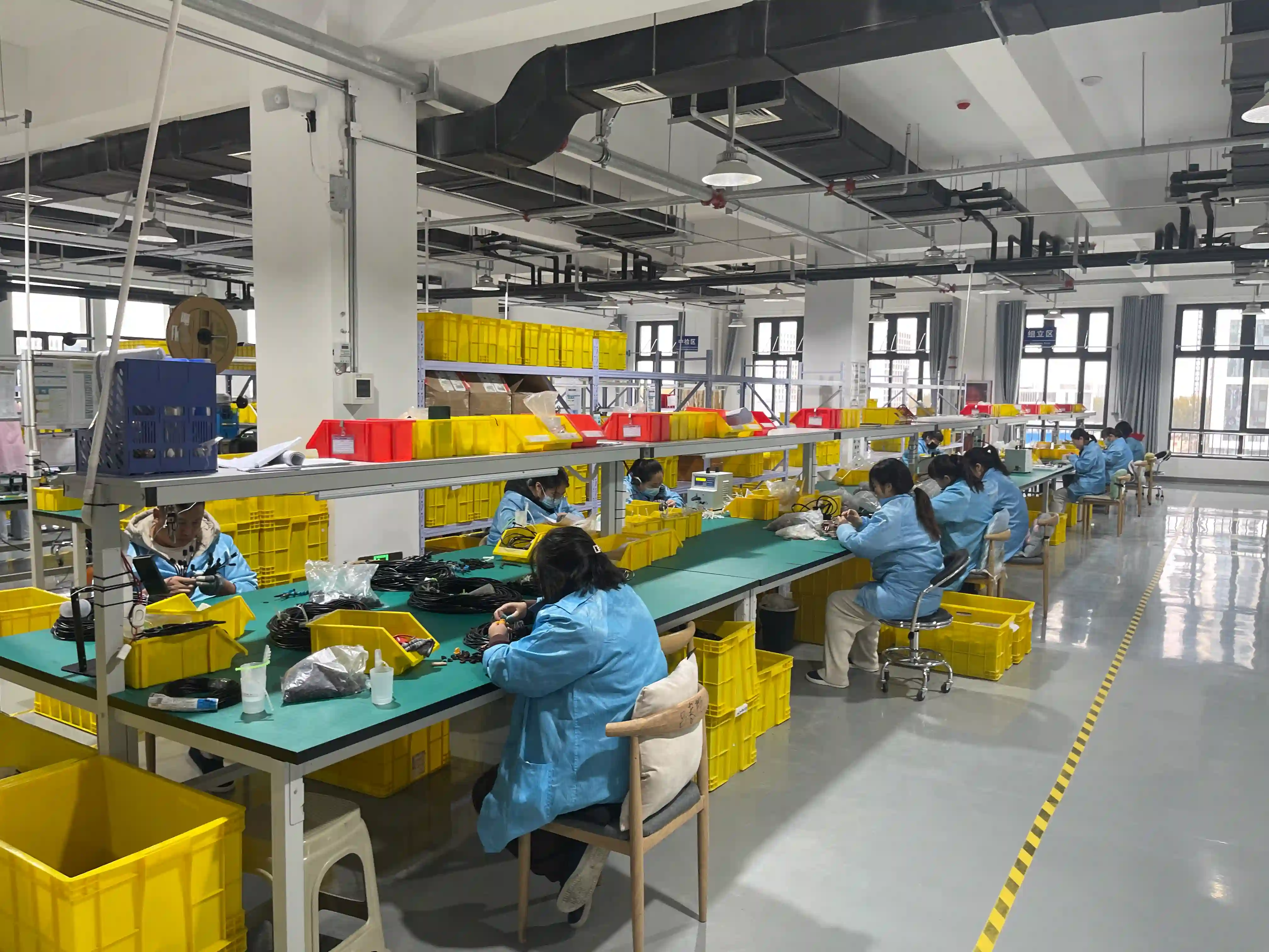
Why Dupont-style cable assemblies need more control than off-the-shelf jumper wires
Many engineering teams start with loose jumper leads because they are fast to source and easy to rearrange. The problem appears when the same wiring has to be repeated across prototypes, test racks, training kits, or low-volume production. Manual sorting, inconsistent lengths, and mixed housing orientations quickly create assembly errors.
A controlled custom assembly solves that by locking the conductor length, colour order, crimp orientation, and grouped housing positions into one documented part number. It is the difference between a temporary wiring method and a repeatable manufactured interconnect.
Buyers also need workmanship that aligns with proven crimping practice and traceable build quality. Industry references such as electrical crimping fundamentals and IPC workmanship standards matter when a prototype harness becomes something technicians or customers rely on repeatedly.
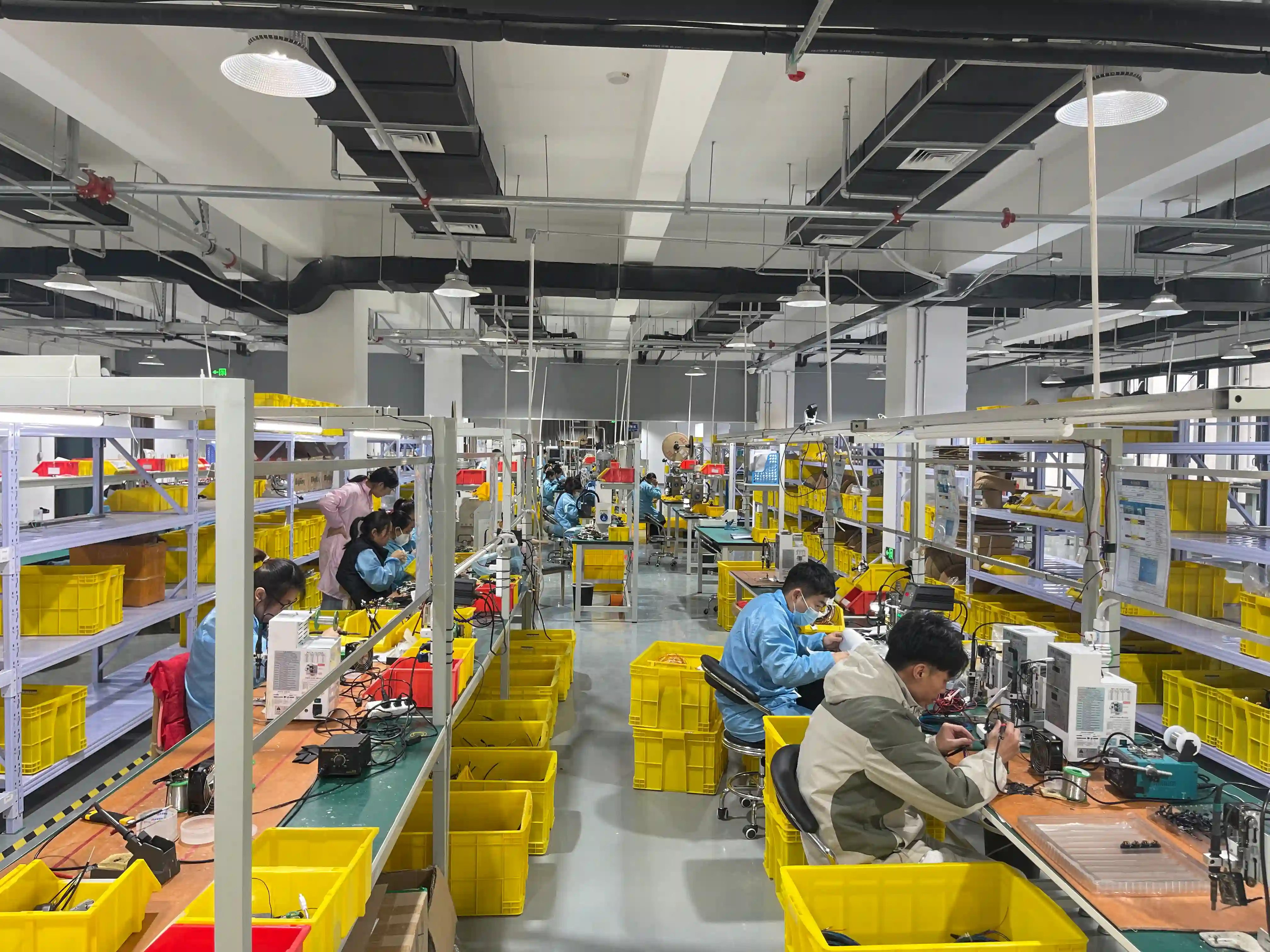
Key advantages of a custom Dupont cable assembly program
These are the practical reasons engineering teams replace generic jumper packs with controlled cable assemblies.
Built Around Real Pin Maps
We manufacture to your actual board header layout, polarity rules, colour sequence, and housing positions instead of treating Dupont cables as generic jumper packs.
From Loose Jumpers to Controlled Harnesses
Prototype wiring can be consolidated into labelled grouped assemblies that install faster, reduce routing errors, and look more professional inside the finished product.
Flexible Connector-End Combinations
Single-pin and multi-position housings can be combined with tinned leads, ferrules, JST, Molex, or board-header ends when your assembly needs a mixed interface.
Better Fit for Lab and Fixture Work
Custom lengths, grouped colours, and repeatable pinout verification are valuable for test racks, diagnostics, educational systems, and engineering validation setups.
Prototype to Repeat Supply
We support engineering samples, low-volume release, and ongoing replenishment so your prototype wiring method does not need to change suppliers mid-program.
Documented Electrical Verification
Every build can be checked against a defined pin map so reversed polarity, swapped colours, and mis-positioned housings are caught before shipment.
Technical scope we commonly support
| Typical Pitch | 2.54 mm single-row and multi-row Dupont-style housings |
|---|---|
| Wire Sizes | Commonly 28 AWG and 26 AWG stranded conductors, with custom options on request |
| Assembly Types | Single jumpers, ribbon sets, breakout harnesses, adapter looms, and mixed-end assemblies |
| End Configurations | Male to male, male to female, female to female, and grouped multi-position housings |
| Build Features | Colour coding, labels, heat shrink markers, custom lengths, bundled sets, and branch points |
| Validation | Continuity, pinout, polarity, length, housing position, and workmanship inspection |
| Production Scale | MOQ 1 prototype through kit builds, pilot lots, and scheduled OEM production |
| Common Use Cases | Embedded electronics, sensor wiring, dev boards, test jigs, controls, and educational kits |
Design review checklist
Define the exact pinout and colour order early so grouped housings do not need manual rework later.
Confirm current level and insertion cycle expectations before assuming a standard jumper wire is enough for production use.
Specify whether wires must stay loose, ribboned, bundled, or branched at a fixed distance from the housing.
Document header pitch, male or female contacts, and row orientation so mating direction is unambiguous.
Use labels or printed IDs when the assembly will be installed by technicians who did not build the prototype.
If the application may outgrow Dupont-style retention, review stronger connector families before tooling and stock decisions are locked.
Common Dupont cable assembly applications
The format is simple, but the use cases range from early-stage prototyping to repeatable internal product wiring.
Embedded Controllers and Development Boards
Interconnects for Arduino, Raspberry Pi, microcontroller headers, daughtercards, and low-voltage embedded systems where quick assembly and clear pin mapping matter.
Sensors, Displays, and Peripheral Modules
Short-run assemblies linking sensors, display modules, relays, LEDs, and low-current peripheral boards inside compact electronic products.
Test Fixtures and Lab Equipment
Grouped cable sets for bench testing, diagnostics, calibration rigs, and production jigs where technicians need repeatable wiring layouts instead of loose jumpers.
Educational and Evaluation Kits
Bundled jumper sets and sub-assemblies for STEM kits, training hardware, and demonstration units that must be easy to identify and hard to mix up.
Prototype Machinery Controls
Low-voltage control looms connecting pilot systems, control panels, switches, and proof-of-concept equipment before the final connector family is frozen.
Replacement and Retrofit Wiring
Custom replacements for internal electronics wiring where imported products or legacy fixtures used undocumented jumper assemblies.
Our manufacturing process
We move from informal jumper-wire prototypes to a documented and testable production assembly without adding unnecessary complexity.
Pin Map and Use-Case Review
We review the mating headers, housing positions, current level, desired colour sequence, installation method, and any service or labelling needs before confirming the design.
Wire and Housing Selection
Our team confirms wire gauge, insulation diameter, conductor stranding, housing style, row count, retention expectations, and any mixed-end terminations.
Prototype Build and Validation
First articles are built for fit, mating, routing, and pinout confirmation so the final layout is proven before repeat production begins.
Controlled Assembly
Assemblies are cut, stripped, crimped, inserted, grouped, labelled, and visually checked to controlled work instructions and revision-managed documentation.
Electrical Test and Release
Completed cables are verified against the approved pin map, then packed in a way that protects housing orientation and colour sequence during delivery.
Need a Dupont cable assembly that can move beyond ad hoc jumper wires?
Send your sample, spreadsheet pin map, or board-header photos. We can convert a working prototype into a repeatable assembly with clearer identification, lower wiring risk, and production-ready documentation. For safety-driven products, we can also align material and process choices with recognised certification expectations such as UL and application-specific compliance needs.
Single jumpers through grouped harness assemblies
Exact colour sequence and housing position control
Prototype, lab, and repeat OEM replenishment
Electrical verification against approved pin maps
Dupont-style connector reference: pitch, contact matching and pin-map acceptance
This public-specification reference and illustrative example contain no measured customer results. Use the exact connector series datasheet and your drawing to define the assembly. Agree inspection criteria at quotation.
Public-specification reference: identify the series before the pitch
'Dupont' is a trade name. In practice, 'Dupont-style' describes generic 2.54 mm (0.100 in) pitch housings and contacts. Name the manufacturer and housing series in the RFQ because the trade name alone does not identify the parts.
| Reference family or feature | Reference dimension | Basis for selection |
|---|---|---|
| Dupont-style | 2.54 mm (0.100 in) pitch | Generic description; confirm the named manufacturer and housing series. |
| Standard 2.54 mm pin-header post | 0.64 mm (0.025 in) square | Post dimension, not pitch; check the mating part against its datasheet. |
| JST XH | 2.50 mm pitch | Different pitch from 2.54 mm; not interchangeable on pitch. |
| JST PH | 2.00 mm pitch | Different pitch from XH and 2.54 mm; identify the exact series. |
| Molex KK 254 | 2.54 mm pitch | Equal pitch does not establish housing/contact compatibility; use the series datasheet. |
For a named JST series, see our JST connector harness capability. Use the connector family comparison alongside the exact part datasheets when preparing the RFQ.
Pitch mismatch accumulates: count the gaps
The reference pitches differ by 2.54 mm − 2.50 mm = 0.04 mm per pitch increment. Over ten increments, the offset is 10 × 0.04 mm = 0.40 mm.
A ten-position row has nine gaps from pin 1 to pin 10. With pin 1 aligned, that span differs by (10 − 1) × 0.04 mm = 0.36 mm. State the start and end positions on the drawing so the calculation uses the correct number of gaps.
Include the pitch and pin-1 reference in your engineering drawing review request; the mating dimensions must follow the selected series datasheets.
Contact retention and current limits need a series reference
- Match housing and contact: Crimp contacts are specific to a housing series. A contact from another series may not lock in, even at the same pitch. Confirm the combination in the connector manufacturer's datasheet.
- Check the retention lance: The lance holds the contact in the housing. Use a gentle pull after insertion to check that it is retained. Agree the inspection method at quotation.
- Specify any force criterion: Retention force depends on the exact series and wire size. Take the criterion from the connector manufacturer's datasheet; a gentle insertion check is not a measured force record.
- Confirm the loaded-pin arrangement: Current ratings depend on the exact series and wire size. Multiple loaded pins may need derating. Use the connector manufacturer's datasheet for the proposed arrangement.
Refer to terminal retention force testing when defining the inspection requirement. Keep the series-specific criterion with the drawing.
Six-way pin map and acceptance record (example template, not a customer result)
ILLUSTRATIVE — no test has been performed for this example.
These single-row examples use ends A and B. The straight-through version connects matching pin numbers. The crossed example swaps only pins 2 and 3. Neither map defines your product; select the required connections on your drawing.
| End A pin | End B: straight-through example | End B: crossed example |
|---|---|---|
| 1 | 1 | 1 |
| 2 | 2 | 3 |
| 3 | 3 | 2 |
| 4 | 4 | 4 |
| 5 | 5 | 5 |
| 6 | 6 | 6 |
Single-row housings are commonly keyed or marked at pin 1. Show each end's pin-1 marker and colour-coded or numbered wire order on the drawing to prevent reversal. A 100% netlist continuity test catches wrong order against that drawing.
- Drawing and selected map: [Enter the customer drawing reference and required connections.]
- Housing/contact pair: [Enter the manufacturer, series and matching part references from the datasheet.]
- Wire order and pin 1: [Enter the colour or number for each wire and identify pin 1 at both ends.]
- Contact retention: [Enter the agreed check, applicable datasheet criterion and actual observation after inspection.]
- Netlist continuity: [Enter the agreed test scope and actual outcome after testing against the drawing.]
Agree the testing and inspection scope at quotation. The fields above are unfilled example fields, not inspection evidence.
What we can and cannot provide
- We can provide: A reference and pin-map example for defining your RFQ. Assembly checks and any supplied records must be agreed at quotation against your drawing and the selected connector datasheet.
- We cannot provide from this example: Measured customer results, a retention-force result or a tested current rating. No such records accompany this illustrative map.
- Connector maker: The exact series datasheet supplies contact matching, current-rating and retention-force requirements. A shared pitch or the word 'Dupont' cannot establish these limits.
- Cable maker and customer: Use the cable maker's datasheet to identify the selected wire. The customer must specify that wire and the required pin map on the drawing; agree the build basis at quotation.
- Customer or system integrator: Owns system-level suitability and compliance. Our agreed assembly checks do not certify the complete machine.
For the contact-to-wire operation, include the selected housing, contact and wire references in your terminal crimping service request. Confirm the matching combination against the connector manufacturer's datasheet.
How a typical dupont cable assembly manufacturing program runs with us
This is an illustrative description of a representative project type, not a specific customer engagement. As a contract assembler we do not publish customer-identifiable data.
Frequently asked questions
Common questions from engineering, test, and product teams specifying Dupont-style cable assemblies.
Related capability and technical resources
Continue with adjacent service and technical content relevant to compact low-voltage cable assemblies.
FFC Cable Assembly
For compact internal electronics interconnects where low profile and controlled routing are critical.
Control Cable Assembly
For more robust signal and low-voltage control looms used in equipment and automation systems.
Connector Selection Guide
Review connector families, retention tradeoffs, and mating-cycle considerations before freezing the design.
Prototype to Production Guide
See how early-stage wiring choices can be converted into a repeatable manufacturing package.