
Control Cable Assembly Manufacturing for Australia
Custom control cable assemblies for industrial automation, robotics, mining, rail, and process equipment. Shielded, labelled, and production-ready builds for PLCs, drives, sensors, actuators, and machine control systems.
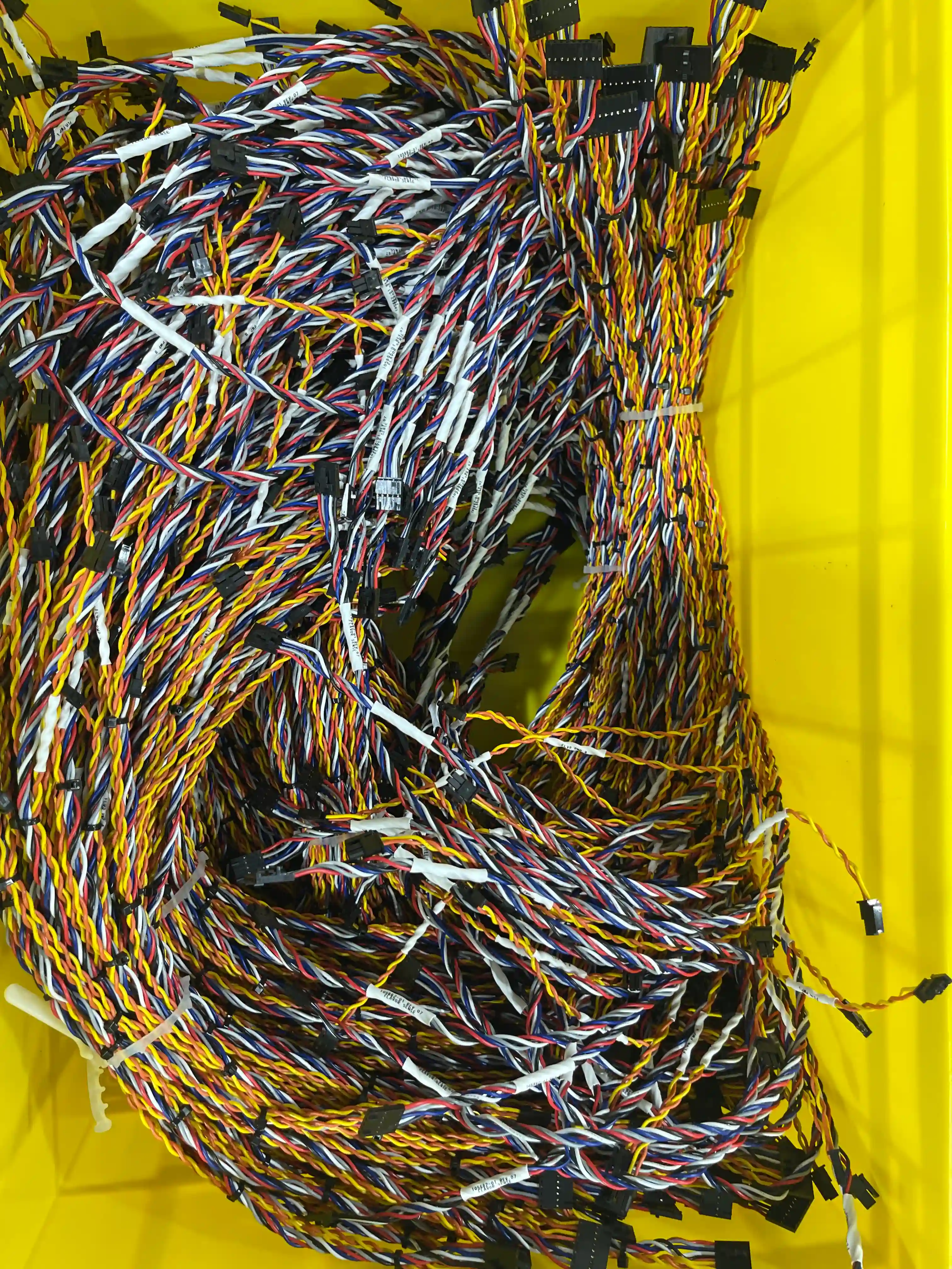
What is a Control Cable Assembly?
A control cable assembly is a purpose-built interconnect used to transmit commands, status signals, sensor feedback, and low-voltage power between machine components. Instead of wiring these circuits manually in the field, the assembly is manufactured, labelled, and tested in advance so installation is faster and more reliable.
These assemblies are common anywhere automation exists: PLC panels, servo drives, conveyors, packaging equipment, robotics, rail subsystems, mining plant, and process skids. Depending on the application, a control cable may include twisted pairs, encoder pairs, power cores, drain wires, overall shielding, branch breakouts, ferrules, or sealed circular connectors.
For Australian OEMs and systems integrators, custom control cable assemblies reduce commissioning time, simplify maintenance, lower wiring errors, and provide a repeatable, documented connection standard across every machine built.

Why Buyers Specify Custom Control Cable Assemblies
Control systems fail when signal wiring is noisy, inconsistent, or difficult to service. Custom assemblies remove those variables.
EMI-Resistant Signal Integrity
Shielding, drain wires, twisted pairs, and controlled termination methods reduce noise problems in VFD, servo, encoder, and PLC circuits.
Built Around Your Pinout
We manufacture to your exact wiring map, conductor colours, labels, breakouts, branch lengths, and mating connector requirements.
Ready for Real Machinery
Cable choices are matched to oil, coolant, abrasion, washdown, vibration, and motion demands found in Australian industrial plants.
Fast Installation on Site
Pre-terminated and labelled assemblies reduce panel wiring time, field errors, and commissioning delays compared with loose cable and manual termination.
Prototype to Repeat Production
We support one-off machine builds, pilot equipment, service spares, and repeat production with revision control and traceable documentation.
100% Electrical Verification
Continuity and pinout verification are standard, with additional insulation, hi-pot, shield, and mechanical checks added to suit the application risk.
Technical Capability Snapshot
Design Inputs We Need to Quote Accurately
If you do not have full documentation yet, send a sample cable, machine photos, or a rough schematic. We can help convert field information into a manufacturable assembly package.
Common Control Cable Assembly Applications
We build assemblies for both new equipment platforms and replacement parts where downtime costs more than the cable itself.
PLC and Control Cabinet Wiring
Assemblies connecting PLC I/O, HMIs, remote I/O racks, safety relays, and terminal blocks inside machine control panels and process skids.
Servo, Encoder and Motion Systems
Low-noise feedback and motor control cables for CNC equipment, packaging machinery, robotic axes, and automated handling systems.
Sensor and Actuator Networks
Reliable field wiring for proximity sensors, valves, limit switches, pressure transducers, and distributed machine I/O.
Mining and Harsh-Environment Equipment
Abrasion-resistant and sealed control cables for conveyors, crushers, mobile plant, washdown zones, and high-vibration installations.
Rail and Transport Systems
Control cable assemblies for signalling, platform equipment, onboard systems, and maintenance tooling where repeatability and documentation matter.
Legacy Machine Replacement
Reverse-engineered spare cables for imported or obsolete machinery where the OEM no longer supports service parts.
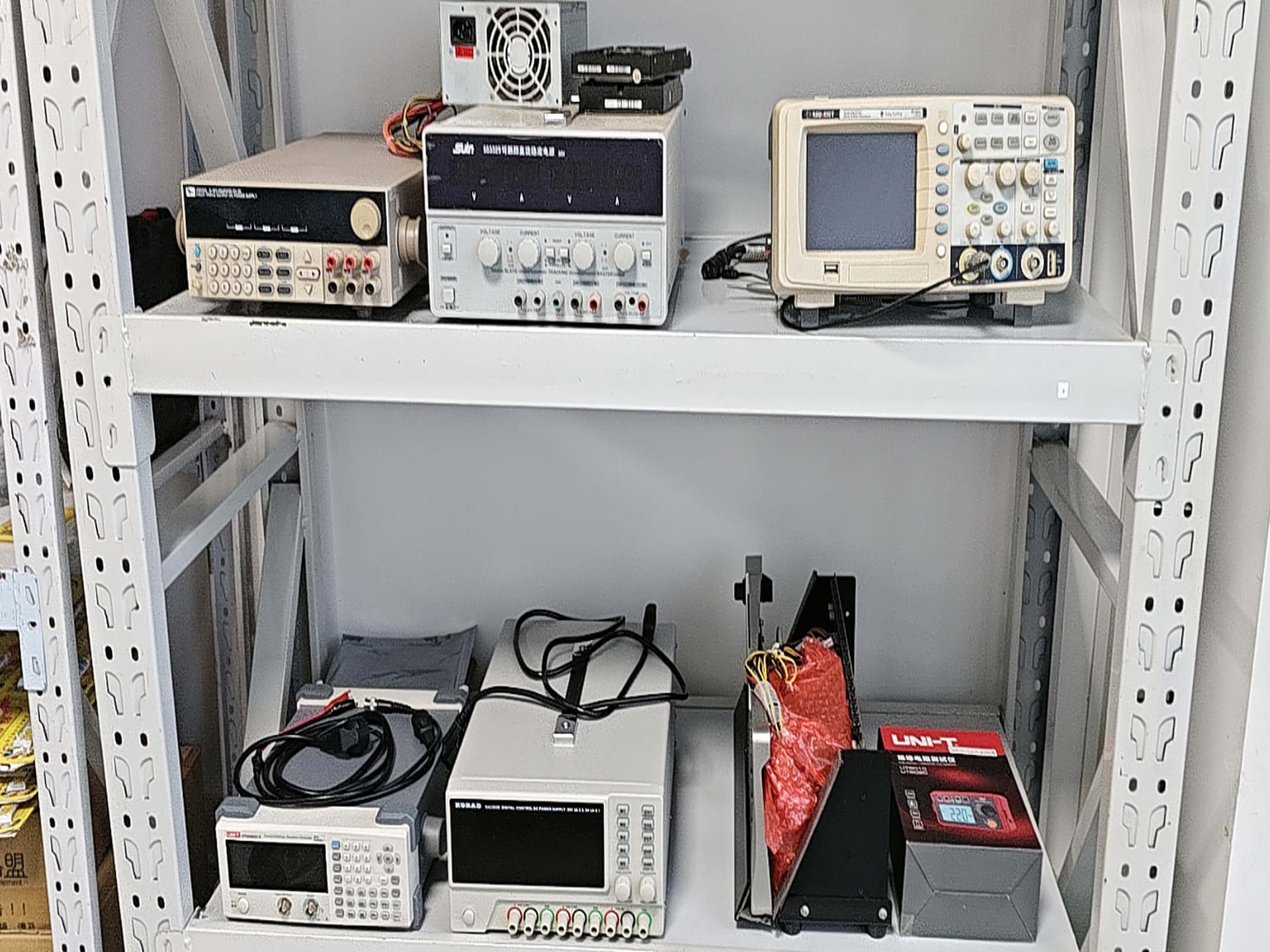
Quality Controls for Signal-Critical Assemblies
Control cable failures are rarely dramatic at first. More often they appear as intermittent alarms, false sensor readings, unstable drives, or random machine stoppages. That is why process control matters as much as raw materials.
Our Build Process
A control cable assembly project moves faster when requirements, documentation, and validation are handled up front.
Requirement Review
We review your drawing, sample, BOM, pinout, environment, motion profile, and certification needs before locking the build approach.
Cable and Connector Selection
Our team confirms conductor size, shielding, jacket material, bend radius, connector family, and strain relief based on the operating conditions.
Prototype Build and Approval
We produce first articles or prototypes for fit, function, and installation checks so issues are corrected before volume release.
Controlled Production
Assemblies are cut, stripped, crimped, terminated, labelled, and inspected to documented work instructions and revision-controlled drawings.
Testing and Final Inspection
Each assembly is electrically verified and visually inspected, with additional testing added for critical signal or insulation requirements.
Control Cable Design Checklist
Most field failures come from missed design assumptions rather than manufacturing defects. These are the details worth locking down before release.
Related Applications and Resources
Control cable reference: conductor sizes, bend radius and encoder pin maps
This public-specification reference gives nominal conductor areas and typical cable-maker bend-radius ranges. It contains no measured customer results. Use the selected cable's datasheet and your drawing for product limits. Agree the test scope at quotation.
AWG and nominal conductor area (reference)
| Wire gauge | Nominal cross-section (mm²) |
|---|---|
| 24 AWG | 0.205 |
| 22 AWG | 0.326 |
| 20 AWG | 0.518 |
| 18 AWG | 0.823 |
| 16 AWG | 1.31 |
These are nominal AWG cross-sections. Common metric control-cable sizes are 0.5, 0.75, 1.0 and 1.5 mm². For example, 20 AWG is 0.518 mm², not exactly 0.5 mm². Confirm the specified size against the cable datasheet and customer drawing.
More cores and larger conductors give a larger outer diameter (OD). The cable datasheet gives the actual OD. Use the wire gauge selection guide alongside that datasheet when specifying conductor size.
Bend radius by installation type (reference)
| Installation type | Typical vendor minimum bend-radius range |
|---|---|
| Fixed installation | Roughly 4–6 × cable OD |
| Repeated flexing | Roughly 7.5–10 × cable OD |
| Drag chain | Roughly 10–15 × cable OD |
These are typical cable-maker ranges, not limits for every cable. The actual cable datasheet governs, and we quote to it. Minimum bend radius = the datasheet multiplier × the datasheet OD. Use the multiplier for the intended installation type.
Use the flex-life and bend-radius guide when recording the selected cable's installation limits on your drawing.
Encoder pairs, shields and servo cable separation
Incremental encoders commonly output A, B and Z channels. Differential versions often add complementary signals. Each true/complement pair normally uses a twisted pair, with an overall shield. Keep the supply connections separate from signal pairs in the pin map. Confirm the actual signals against the product datasheet and customer drawing.
Specify A with A-, B with B-, and Z with Z- where those complementary signals are used. See the multi-pair cable selection guide when documenting these pair assignments.
The customer's EMC plan determines shield termination: 360° at the connector or gland, and one end or both ends. Use the shield termination guide to document the method required by that plan.
Servo systems usually use separate motor power and encoder feedback cables. VFD/inverter output cables should be VFD-rated. See our VFD cable assembly page and confirm the selected cable's rating from its datasheet.
Eight-core encoder pin map and acceptance checklist (example template, not a customer result)
Illustrative only — no measured values or completed test results
This example maps connector A pins 1–8 to connector B pins 1–8. The +24 V label is illustrative, not a supply requirement for every encoder. Replace these assignments with the customer drawing and product datasheet requirements before use.
| Connector A pin | Connector B pin | Illustrative signal | Pin-map grouping |
|---|---|---|---|
| 1 | 1 | +24 V | Supply |
| 2 | 2 | 0 V | Supply |
| 3 | 3 | A | A / A- twisted pair |
| 4 | 4 | A- | A / A- twisted pair |
| 5 | 5 | B | B / B- twisted pair |
| 6 | 6 | B- | B / B- twisted pair |
| 7 | 7 | Z | Z / Z- twisted pair |
| 8 | 8 | Z- | Z / Z- twisted pair |
Record the overall shield and drain separately from the eight core assignments. Leave the termination at each end to the customer's EMC plan; this example assigns no connector pin to the drain.
- Pin map and pair assignments: Enter the customer drawing reference and the required from-to connections.
- Continuity and unrelated nets: Record whether each connection matches the netlist and unrelated nets are not shorted. Results remain unfilled in this example.
- Insulation resistance: Enter the test voltage and pass threshold from the customer specification. Leave the measured result unfilled until testing.
- High-potential test: Enter the test voltage and pass threshold from the customer specification. Leave the result unfilled until testing.
- Shield and drain: Enter the termination method at each end from the customer's EMC plan.
Agree which electrical testing items and records are required at quotation. No test voltages, pass thresholds or outcomes are assumed here.
What we can and cannot provide
- We can provide assembly electrical verification: A from-to netlist test checks wire destinations and shorts between unrelated nets against the customer's pin map. Agree the record format at quotation.
- We can provide specified insulation tests: Insulation-resistance and high-potential test voltages and pass thresholds come from the customer specification. Agree their scope at quotation.
- We cannot present this example as test evidence: It is an unfilled template, with no customer measurements or results.
- We cannot set universal component limits: The cable maker's datasheet governs OD and bend radius. Confirm connector requirements against the connector maker's datasheet and the customer drawing.
- We do not certify machine-level compliance: The customer owns the pin map, EMC plan and acceptance requirements. The system integrator owns machine-level validation; assembly checks cover the agreed test scope.
Use engineering drawing review to define the pin map, datasheet limits and customer acceptance requirements for quotation.
How a typical control cable assembly manufacturing program runs with us
This is an illustrative description of a representative project type, not a specific customer engagement. As a contract assembler we do not publish customer-identifiable data.
Control Cable Assembly FAQ
Questions buyers and engineering teams ask before approving an automation cable build.
Need a Reliable Source for Custom Control Cable Assemblies?
Send your pinout, sample, drawing, or machine photos. We will review cable construction, connector options, shielding strategy, and lead time before quoting.