A Tier-2 automotive supplier in Victoria shipped 2,000 wire harnesses to a seat assembly plant. Three weeks later, 58 units came back with intermittent open circuits. Root cause: the crimping station had drifted 0.15mm above the terminal manufacturer's crimp height specification, and nobody caught it because the facility had no crimp force monitoring on that applicator. Total cost of the recall, rework, and expedited re-shipment: AUD $94,000.
A different manufacturer running the same terminal and wire gauge caught an identical drift on the third crimp cycle — their crimp force monitor flagged a 12% force deviation, the operator stopped the machine, re-set the die, and ran a cross-section verification before resuming. Zero defective harnesses left the building. Same wire, same terminal, different process discipline. This guide walks through every step of that process so you know exactly where quality is built — or lost.
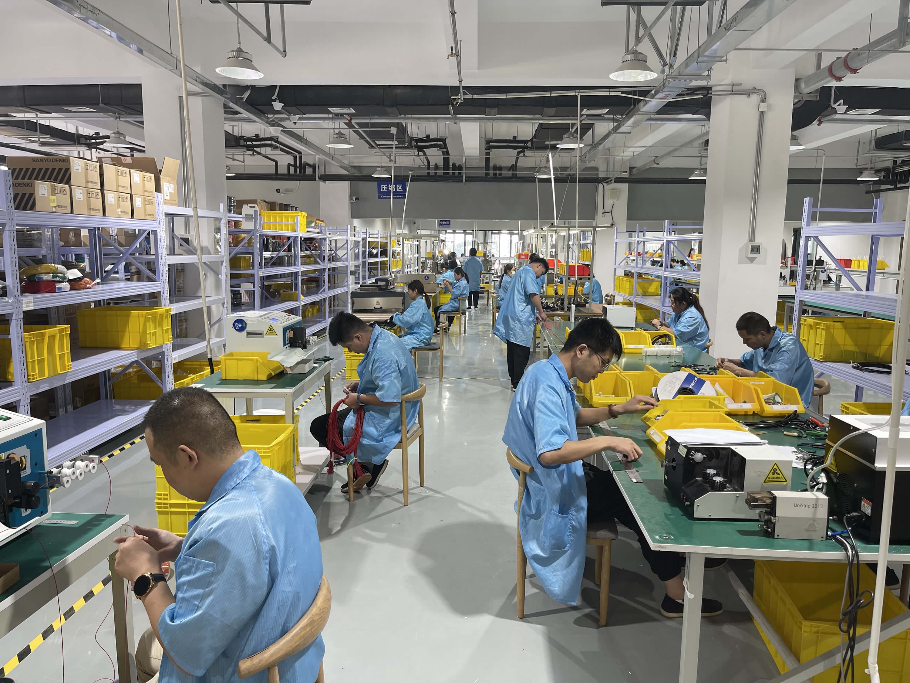
Discrete production steps from design to packaging
Manual labour content in typical wire harness production
Electrical test rate required per IPC-A-620 Class 2/3
Wires per hour on automated cut-strip-mark machines
"Wire harness manufacturing looks simple on paper — cut wire, crimp terminals, plug them in. In practice, 80% of field failures trace back to a process step that was rushed or skipped. The manufacturers who invest in process controls at each station are the ones who ship at 50 ppm defect rates instead of 5,000."
Hommer Zhao
Engineering Director, Custom Wire Assembly
Step 1: Design Review & Engineering Validation
Every wire harness starts with a documentation package: a wiring schematic, connector pinout table, bill of materials (BOM), and either a 2D routing drawing or 3D CAD model. The engineering team reviews this package for manufacturability before any material is ordered. Per DFM best practices, this review catches issues like incompatible terminal-to-wire gauge pairings, bend radii below minimum specs, and connector housings that require non-standard tooling.
The output is an approved manufacturing traveller — a document that follows the harness through every production step. It specifies wire lengths (with tolerances of ±3mm for most applications), strip lengths per terminal type, crimp specifications, test parameters, and inspection criteria. Without this document, operators make assumptions, and assumptions create defects.
Step 2: Material Procurement & Incoming Inspection (IQC)
Raw materials for a wire harness fall into five categories: wire (copper conductors with PVC, XLPE, PTFE, or silicone insulation), terminals and contacts, connector housings, protection materials (tape, sleeving, conduit, heat shrink), and hardware (clips, grommets, cable ties). Material procurement for a 500-unit production run typically takes 1–3 weeks, with specialist connectors like Deutsch DT series or Amphenol mil-spec contacts often driving the longest lead times.
Incoming Quality Control (IQC) verifies every material lot before it enters production. For wire, this means checking conductor gauge with a micrometer, verifying insulation colour against the applicable colour standard, and measuring insulation thickness. For terminals, IQC confirms the part number, plating type (tin, gold, silver), and that crimp barrel dimensions match the approved specification. A detailed IQC process is covered in our incoming inspection guide.
Step 3: Wire Cutting

Automated cut-to-length machines pull wire from bulk spools, measure to the programmed length, and cut. Modern machines like the Komax Alpha 550 process 5,000+ wires per hour with a length accuracy of ±1mm. Each cut wire receives a batch code linking it back to the wire spool lot number — essential for traceability if a defect surfaces downstream.
For harnesses with mixed wire gauges (common in automotive and industrial control applications), the cutting sequence is programmed to match the BOM, with wire gauge changes requiring a spool swap and machine recalibration. High-volume runs group identical wire specifications together to minimise changeover time.
Step 4: Wire Stripping
Stripping removes insulation from wire ends to expose the conductor for termination. Strip length is dictated by the terminal type: a standard open-barrel crimp terminal requires 3–5mm of exposed conductor, while a solder cup connector might need 6–8mm. The three main stripping methods are rotary blade (best for standard PVC and XLPE insulation), V-blade (for thin-wall automotive wire), and thermal stripping (required for PTFE and silicone insulation that would be damaged by mechanical blades).
The critical quality parameter is nick-free stripping: the blade must cut through insulation without scoring the conductor strands beneath. A single nicked strand in a 19-strand 18 AWG conductor reduces the wire's cross-sectional area by 5.3%, which increases resistance at that point and creates a potential hot spot under load. IPC-A-620 Class 2 permits a maximum of 10% strand damage; Class 3 (aerospace and medical) allows zero.
Step 5: Wire Marking & Labeling
Wire marking assigns a unique circuit identifier to each conductor, enabling correct routing during assembly and reliable troubleshooting in the field. Common marking methods include hot-stamp printing (durable, works on most insulation types), inkjet printing (fast, good for high-volume runs), laser marking (permanent, required for mil-spec and aerospace harnesses per AS50881), and heat-shrink sleeves with printed text (used when the wire insulation colour doesn't accept ink). Our labeling and marking guide covers material selection for harsh environments.
On automated cut-strip-mark machines, marking happens inline: the machine cuts the wire, strips both ends, and prints the circuit ID in one pass. For low-volume or prototype harnesses, operators apply pre-printed sleeves or flag labels manually.
Step 6: Terminal Crimping

Crimping is the most critical process step in wire harness manufacturing. A terminal crimp creates a gas-tight mechanical and electrical connection between the wire conductor and the terminal contact. Automatic crimping machines (like the Komax Kappa series) process crimps at 3,600–7,200 terminals per hour. Semi-automatic bench presses handle lower volumes and non-standard terminal types. For full crimp quality inspection criteria, see our dedicated guide.
Four quality gates protect crimp integrity:
- Crimp Force Monitoring (CFM) — sensors on every press cycle detect force deviations as small as ±5%, flagging missing strands, wrong wire gauge, or worn tooling in real time
- Crimp Height Measurement — a micrometer verifies the compressed crimp barrel height against the terminal manufacturer's specification (typical tolerance: ±0.05mm)
- Cross-Section Analysis — a destructive test on first-article and periodic samples, cutting through the crimp to verify 80% conductor compression with no strand fallout per IPC-A-620
- Pull Testing — applies axial force to the crimped connection, verifying it meets minimum tensile strength (e.g., 50N for 22 AWG, 180N for 14 AWG per IPC/WHMA-A-620 Table 8-1)
"Crimping is where we see the biggest gap between good manufacturers and bad ones. Anyone can buy an automatic crimping machine. The difference is whether they run crimp force monitoring on every cycle, do cross-sections on first article, and retrain operators when they change terminal types. We reject more supplier samples at the crimp station than at any other step."
Hommer Zhao
Engineering Director, Custom Wire Assembly
Step 7: Connector Housing Insertion
Terminated wires are inserted into connector housings according to the pinout diagram. Each crimped terminal clicks into a specific cavity position within the housing. Operators verify seating by listening for the retention click and performing a gentle tug test — a properly seated terminal resists 10–20N of pull force. Mis-seated terminals that pass the retention latch but sit 0.5mm proud of the housing face will cause intermittent contact failures when the mating connector is plugged in.
For connectors with Terminal Position Assurance (TPA) features — common on Deutsch DT/DTM, TE AMPSEAL, and Molex MX150 series — a secondary lock slides into place after all terminals are inserted. The TPA physically prevents any partially seated terminal from remaining in the housing. This step adds seconds to assembly time but eliminates the most common connector-related field failure: backed-out pins.
Step 8: Form Board Assembly & Routing
The form board (assembly jig) is a full-scale template mounted on a flat or tilted work surface. Routing pins, connector holders, and branch guides are positioned to match the harness design drawing at 1:1 scale. Technicians lay each wire along the designated routing path, secure branch breakouts, and clip connectors into their holders. For complex harnesses with 50+ circuits, the form board reduces assembly time by 30–40% compared to free-form assembly because every decision — which wire goes where, which branch breaks out at which point — is already made by the board layout.
In high-volume production, multiple identical form boards run in parallel with a conveyor or carousel system. Each station handles one sub-assembly task (e.g., Station 1 routes the main trunk, Station 2 adds branch circuits, Station 3 installs breakout connectors). This line-balancing approach distributes labour evenly and increases throughput without rushing any single step.
Assembly Tip
For harnesses routed through tight enclosures, verify bend radius requirements on the form board before production starts. A routing pin placed too close to a connector exit forces the wire bundle below minimum bend radius, which causes conductor fatigue and eventual failure under vibration.
Step 9: Bundling & Protection
Once routed, the wire bundle is secured and protected against abrasion, heat, moisture, and EMI. Protection material selection depends on the operating environment. PVC tape provides basic abrasion resistance at the lowest cost. Woven PET cloth tape handles temperatures to 150°C and is the standard for engine bay harnesses. Non-woven fleece tape absorbs vibration and prevents rattle — the preferred choice for automotive cabin harnesses where NVH performance matters.
For harsher environments, braided nylon sleeving (rated to 120°C, cut-through resistant), split convoluted tubing (flexible, easy to install around pre-terminated harnesses), and heat-shrink tubing (provides a sealed, moisture-proof covering) are used individually or in combination. Mining and defence harnesses often require multiple protection layers: heat shrink at connector interfaces, convoluted tubing along the main trunk, and additional abrasion sleeving at chassis pass-through points.
Step 10: Soldering & Special Terminations
Not every termination uses a crimp. Solder cup connections (common on D-sub, circular mil-spec, and RF connectors) require hand soldering with temperature-controlled stations set to 300–370°C depending on the solder alloy. Inline splice joints combine two or more wires at a mid-span point using butt splices, solder sleeves, or ultrasonic welding. Ultrasonic welding bonds copper conductors without solder or flux — it produces a solid-state joint with lower resistance than a crimped connection and is the standard for EV battery harness interconnects.
IPC J-STD-001 governs solder joint quality. A compliant solder joint shows smooth, concave fillet formation with complete wetting of the solder cup and conductor. Cold joints (grainy texture, convex profile) and insufficient joints (less than 75% cup fill) are rejected. For manufacturers transitioning to lead-free soldering (required for RoHS-compliant harnesses), SAC305 alloy (96.5% tin, 3% silver, 0.5% copper) requires higher iron temperatures and longer dwell times than traditional Sn63/Pb37.
Step 11: Electrical Testing

Every finished wire harness undergoes 100% electrical testing — no sampling, no exceptions. IPC-A-620 Class 2 and Class 3 both mandate full electrical verification. The three core tests are continuity, hi-pot, and insulation resistance, each targeting a different failure mode. For a deeper technical breakdown of test parameters and pass/fail criteria, see our complete testing guide.
| Test | What It Detects | Typical Parameters | Pass Criteria |
|---|---|---|---|
| Continuity | Opens, shorts, mis-wires | Low-voltage signal per pin pair | < 50 mΩ per connection |
| Hi-Pot (Dielectric Withstand) | Insulation breakdown, pinhole defects | 500–1,500V AC for 60 seconds | No breakdown, leakage < 5mA |
| Insulation Resistance (Megohm) | Moisture ingress, contamination, degraded insulation | 500V DC applied between conductors | ≥ 100 MΩ per IPC-A-620 Class 2 |
Automated test fixtures use spring-loaded probe pins that mate with every connector on the harness simultaneously, running the full test sequence in 15–45 seconds. The fixture design cost (AUD $2,000–$15,000 depending on harness complexity) pays back quickly: automated testing eliminates the operator-dependent variability of manual point-to-point probing and produces a digital test record for every harness.
Step 12: Final Inspection & Packaging
Final inspection is a visual and dimensional check against the IPC/WHMA-A-620 standard. Inspectors verify connector seating, wire routing matches the drawing, protection materials are intact, labels are legible, and there are no cosmetic defects (nicked insulation, loose cable ties, adhesive residue). Dimensional verification confirms overall harness length and branch breakout positions against the engineering drawing tolerances.
Packaging follows customer specifications. Standard packaging uses anti-static bags or polyethylene wrapping with foam dividers to prevent connector damage during transit. Automotive OEM harnesses ship in dedicated returnable totes with moulded cavities that hold each harness in its installed shape. Every package is labelled with part number, batch code, quantity, manufacture date, and a unique serial number that links back to the full production traveller and test records.
"Packaging is the step most manufacturers treat as an afterthought, and it shows. We had a customer receive 100 defence harnesses where two connectors had been crushed in transit because the packaging didn't immobilise the connector shells. Now every packing specification gets engineering sign-off just like the wiring diagram. A AUD $2 foam insert prevents a AUD $20,000 rework."
Hommer Zhao
Engineering Director, Custom Wire Assembly
Manual vs. Automated: Which Steps Can Be Automated?
Wire harness manufacturing remains one of the most labour-intensive assembly processes in electronics. Unlike PCB assembly where SMT machines place thousands of components per hour, harness geometries are too variable for full robotic assembly. According to industry data published by Assembly Magazine , wire harness production is approximately 50–70% manual labour globally. Here is the automation potential for each step:
| Step | Automation Level | Typical Equipment | Notes |
|---|---|---|---|
| Wire Cutting | Fully Auto | Komax Alpha, Schleuniger | 5,000+ wires/hour |
| Wire Stripping | Fully Auto | Inline with cut machine | Rotary or V-blade |
| Wire Marking | Fully Auto | Inkjet, hot-stamp, laser | Inline with cut machine |
| Terminal Crimping | Semi/Full Auto | Komax Kappa, bench press | Auto for standard terminals |
| Connector Insertion | Manual | Hand tool + fixture | Too many housing variants |
| Form Board Assembly | Manual | 1:1 jig board | Highest labour content step |
| Bundling & Taping | Manual | Hand taping + heat gun | Auto taping on straight runs only |
| Electrical Testing | Fully Auto | Custom test fixture + tester | 15–45 sec per harness |
This automation split explains why wire harness manufacturing has not followed PCB assembly to full lights-out production. The form board assembly step alone accounts for 40–60% of total production time, and the physical dexterity required to route flexible wires through complex 3D paths remains beyond current robotic capabilities for anything except the simplest straight-run harnesses.
Common Manufacturing Defects & Prevention
Understanding where defects originate helps buyers evaluate manufacturers and helps engineers design harnesses that are easier to build correctly. According to IPC industry data, approximately 70% of wire harness defects originate during the manual assembly steps (Steps 7–9).
| Defect | Process Step | Root Cause | Prevention |
|---|---|---|---|
| Under-crimped terminal | Crimping | Worn die, wrong applicator setup | CFM + first-article cross-section |
| Backed-out pin | Connector insertion | Terminal not fully seated past retention latch | TPA clips + tug test every pin |
| Nicked conductor | Stripping | Blade depth too deep, dull blades | Blade calibration + magnified inspection |
| Mis-wire / wrong pin position | Connector insertion / routing | Operator reads pinout incorrectly | 100% continuity test catches every mis-wire |
| Insulation damage at bend point | Form board routing | Bend radius below wire minimum | Form board validation before production |
Related Articles
Crimp Quality Inspection Guide
Cross-section analysis, crimp height specs, and pull test criteria per IPC-A-620 for terminal crimp verification.
Wire Harness Testing Guide
Continuity, hi-pot, and insulation resistance testing methods for verifying harness integrity after assembly.
IPC/WHMA-A-620 Standard Guide
Complete guide to Class 1, 2, and 3 workmanship standards for cable and wire harness assemblies.
References
- IPC/WHMA-A-620D — Requirements and Acceptance for Cable and Wire Harness Assemblies. IPC — Association Connecting Electronics Industries. Wikipedia: IPC (electronics)
- Wiring Harness Manufacturers Face Three Big Challenges. Assembly Magazine, 2022. assemblymag.com
- IPC J-STD-001 — Requirements for Soldered Electrical and Electronic Assemblies. IPC Standards. Wikipedia: Soldering
Frequently Asked Questions
What are the main steps in wire harness manufacturing?
Wire harness manufacturing follows 12 steps: design review, material procurement and incoming inspection, wire cutting, wire stripping, wire marking, terminal crimping, connector housing insertion, form board assembly and routing, bundling and protection, soldering and special terminations, electrical testing (continuity, hi-pot, insulation resistance), and final inspection with packaging. Each step has specific IPC-A-620 quality criteria that must be met before the harness advances.
I need 500 custom wire harnesses for mining equipment — what should I expect for lead time and which steps take the longest?
For 500 custom mining harnesses, expect 4–8 weeks total lead time. Material procurement takes 1–3 weeks (mining-spec IP67+ connectors and high-temperature wire often have longer lead times). Form board assembly and routing is the most labour-intensive step, typically consuming 40–60% of total production time. Electrical testing runs every harness at 100% — no sampling. First-article approval adds 3–5 days at the start of the run.
Which wire harness manufacturing steps can be automated?
Wire cutting, stripping, and marking are fully automatable at 5,000+ wires per hour. Terminal crimping uses auto applicators with crimp force monitoring. Electrical testing uses automated fixtures. However, connector insertion, form board assembly, and bundling remain manual because harness geometries vary too much for robotic handling. The industry is approximately 50–70% manual labour overall.
How do you ensure crimp quality in wire harness production?
Crimp quality relies on four verification methods: crimp force monitoring (CFM) on every cycle, crimp height measurement against the terminal manufacturer's specification (±0.05mm tolerance), cross-section analysis on first-article and periodic samples per IPC-A-620, and pull testing to verify minimum tensile strength per wire gauge. A properly crimped connection shows 80% conductor compression with no strand fallout.
What is a form board and why is it used in wire harness assembly?
A form board is a full-scale assembly template with routing pins, connector holders, and branch guides positioned to match the harness design at 1:1 scale. It ensures every harness in a production run is dimensionally identical and eliminates routing errors. For complex harnesses with 50+ circuits, form boards reduce assembly time by 30–40% versus free-form assembly. High-volume lines use multiple identical boards in a carousel system.
What electrical tests are performed on finished wire harnesses?
Three core tests: continuity testing verifies every pin-to-pin connection with no opens or shorts; hi-pot testing applies 500–1,500V AC to verify insulation integrity; and insulation resistance (megohm) testing measures leakage current between conductors, with a minimum of 100 MΩ required for IPC-A-620 Class 2. Automated test fixtures run the full sequence in 15–45 seconds with a digital record for every harness.